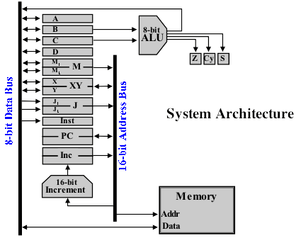
In this post I’ll continue to try and explain away the various bits of the architecture that will make up my relay computer project — this time it’s the Arithmetic Logic Unit (ALU). Here (yet again) is the architecture I’ll be building against (from the Harry Porter Relay Computer)
The Arithmetic Logic Unit (ALU) sits at the very heart of the computer and without it you wouldn’t be able to do much at all … you could certainly move data back and forth between the memory and registers but that’d be about it. As you might have guessed from the name it allows the computer to perform arithmetic and logic functions. Some ALUs have a myriad of functionality available but this architecture takes a good balance between simplicity and functionality — the idea being that you can perform more complex functions by using a combination of simpler ones (subtraction can be performed by negating a number then adding it and multiplication can be performed by repeated adding). This does mean that the computer takes longer to do some things, like subtraction and multiplication, but it’s much simpler to construct as a result.
The ALU takes its inputs from the B and C registers (although for some operations C is ignored). The result the ALU produces goes back on to data bus. In theory you could physically store the result in any of the writable 8-bit registers (except B and C which are used as inputs) however in practice the result would be placed in A or D.
For the arithmetic side of things the ALU can perform two operations: Add and Increment. Add takes the values in B and C and produces the sum B + C. Increment takes the value in B (ignoring C) and produces the sum B + 1. There are five logic functions: AND (and), OR (inclusive or), XOR (exclusive or), NOT (not) and SHL (shift left). AND, OR and XOR operate on B and C inputs as follows:
B    10101010
C    11001100
-------------
AND  10001000
OR   11101110
XOR  01100110
So AND for a given bit is 1 when both B and C are 1. OR for a given bit is 1 when either B or C (or both) are 1. XOR for a given bit is 1 when either B or C (but not both) are 1. When we use ‘or’ in everyday speech, of course, we are usually using the exclusive or (you can have tea or coffee … not a steaming hybrid of teffee). The NOT function works on the B input only and operates as follows:
B    10101100
-------------
NOT  01010011
That is, NOT for a given bit is 1 when B is 0 and 0 when B is 1. Finally we have SHL (shift left) which operates on the B input only as follows:
B    10101100
-------------
SHL  01011001
This moves each bit in B one place to the left with the left/highest bit rotated back to the right/lowest bit.
In order to be even more use to a programmer the ALU contains three special 1-bit ‘condition registers’. These are set following each ALU operation as follows:
- Z - Zero. Set when the ALU result is zero (all bits are 0).
- Cy - Carry. Set when an ALU addition or increment resulted in a bit being carried. An example of where this would be set is when adding 1 to the number 255 (11111111) … the 1 would ripple through the result creating 00000000 with 1 carried. The carry condition shows in this case that we’ve added one more than we could hold in an 8-bit value (what’s known as an overflow). Actually, the ALU can use this flag to pull off 16-bit addition - you would add the lower 8-bit numbers together then add the upper 8-bit numbers along with an extra 1 if the carry condition was set on the first addition (just as you would when doing long addition by hand with decimal numbers).
- S - Sign. Set when the ALU result has the left/highest bit set. This would mean the value is negative when we’re treating the results as signed numbers. If we’re treating the numbers as unsigned then this condition has no meaning … effectively it will be set when the number is 128 or more.
Usually the condition registers are used to make decisions/jumps in a program so for example if I wanted to check if two signed numbers added together produce a negative result I would load one in to register B and the other in register C then perform the add and check the sign condition … if the sign condition is set then the result was negative and I can jump to a different line in the program, if not I can carry on with the next line as normal. This actually leads quite nicely on to my final instalment on the architecture … how a program actually executes and controls the computer.