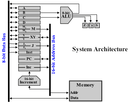
So, the last post didn’t quite wrap up this ‘mini-series’ but hopefully this one will. Continuing on with how the Programming and Control of the computer happens here again, for the last time (really last time), is the architecture I’ll be building against (from the Harry Porter Relay Computer)
In the last post I covered an example of the steps required to subtract 6 from 10 (with 6 placed in register B and 10 in register C beforehand) and also that each step is represented by an opcode which is placed in the Instruction register so the computer can work out the sequence of actions to take to perform the step. The collection of program steps are stored in the memory along with any data required and so a full program to subtract 6 from 10 would look as follows in memory:
0001  11000000    Set M-Register to 0x0016
0002  00000000
0003  00010110
0004  10010010    Load Register C from Memory (Address in M)
0005  11000000    Set M-Register to 0x0017
0006  00000000
0007  00010111
0008  10010001    Load Register B from Memory (Address in M)
0009  10000110    ALU Not to A
000A  00000001    Move A to B
000B  10000010    ALU Increment to A
000C  00000001    Move A to B
000D  10000001    ALU Add to A
000E  11000000    Set M-Register to 0x0018
000F  00000000
0010  00011000
0011  10011000    Store Register A into Memory (Address in M)
0012  10101110    HALT
0013  00000000
0014  00000000
0015  00000000    Data Starts Below
0016  00001010    10
0017  00000110    6
0018  00000000    0 (Result will be stored here)
First thing to note is the values in the left column are the memory addresses (shown in hexadecimal) — you can see that this increases by one for each sequential byte in the program. The second column is the opcode itself and there’s a couple of new opcodes thrown in here. Firstly the ‘Load 16-bit immediate’ which places a 16-bit value into the M register by loading the first byte that follows the opcode into M2 then the next byte into M1. There is also the Load and Store opcodes which using the address stored in the M register either store a value from a given register to memory or load a register with a value in memory. Finally there is the Halt opcode which stops the computer from executing the program. Notice again that the data and program both sit in memory and the values 10 and 6 are stored following the program.
So, how does the program get in memory in the first place? Effectively you would set the target address for the first line of the program on the address bus, enter the opcode on the data bus then load the value into memory (all by using toggle switches). Next you set the target address one slot higher, set the next opcode and load the value into memory. This sequence is repeated until the program is all loaded in. Needless to say if you get a power cut then you’ll have to start again from scratch. Incidentally the Phil Ryals RC-3 Relay Computer makes this all a little bit easier by letting the user set the opcode and then flick a single switch which stores the value in memory and increments the address by one.
With the program in memory we’re all set to let the computer start executing it. We just need to ensure the Program Counter register is pointing at the first line of the program (typically at address 0) and we’re good to go. Starting the computer up it will now perform the following steps:
- Read the value in Memory (at the address pointed to by the Program Counter) into the Instruction Register.
- Increment the Program Counter by 1 (using the 16-bit incrementer)
- Decode the Instruction Register and perform the operation
- Repeat
This allows a sequential program (like the subtract one above) to run through to the end as intended. If we want to do something a little more complex that’s where jumps come in so that depending on the result of the ALU condition registers we can jump to a different line of the program by setting the Program Counter to an address pre-loaded into the J register. That’s basically it … in the next post I’ll reveal the full list of opcodes this computer will implement along with the assembly mnemonics for each although I won’t go into too much detail on it for now as it’ll be quite a while before the computer is at the stage where its ready to be programmed.