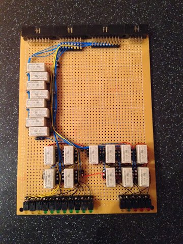
The ALU Control Card is now complete and looks like this:

This card was, on the whole, much simpler and quicker to put together than previous cards (despite me initially messing up the zero detection relay positions). As the card isn’t too busy I’ve arranged the wiring away from the empty part of the card so there’s room for future expansion or modifications if needed in the future. Not entirely sure what they’d actually be but you never know.
As is now customary when I’ve completed a card I’ve created a video replete with voiceover track attempting to demonstrate the card in action and explain what’s going on. Here it is:
The completion of the control card actually represents a bit of a mini-milestone … combined with the logic and arithmetic cards I now have a potentially fully functional ALU. I say potentially because I don’t actually have any physical way of connecting the three cards together yet and so my next task will be to complete the card backplane … once that’s done then I should be able to demonstrate the full ALU.
Following completion of the backplane then I’ll start work on the B/C register card so that I can load values into the ALU from the data bus (rather than directly via the B/C bus) and then following that it’ll be the A/D register which can then store the result produced by the ALU. With all five cards in place (which represents a fair amount of effort) it should be possible to perform simple operations in full such as subtraction and multiplication and to show how the ALU would perform the logic/arithmetic behind conditional jumps (such as value = 0, valueA < valueB, valueA <> valueB etc).
In other news I’ve also received the aluminium profile for the first half of my enclosure so I’ll post about how that’s going pretty soon … although after putting some of the case together already I expect it’ll take a while for my hands to recover from driving the self tapping screws in before I’ll be able to type again.