Load Register
Loads a value from memory into register A, B, C or D. The memory address is taken from the 16-bit M Register.
rr = destination register (00-A, 01-B, 10-C, 11-D)For a while now my computer has been missing its final three instruction classes … and two of them are ‘up there’ alongside branching in terms of overall importance for the capability of my relay computer. The irony is, of course, that these instructions are already present on the controller PCB because you can’t ‘half design a PCB’ but to ‘play fair’ I’ve not soldered in the relays yet because I haven’t explained them yet in this blog … but that’s about to change.
Those three instructions are LOAD, STORE and INCXY. The important two are LOAD and STORE and it’s with those that my computer reaches an important milestone where much more complicated programs can be run. Let’s take a look at each in turn.
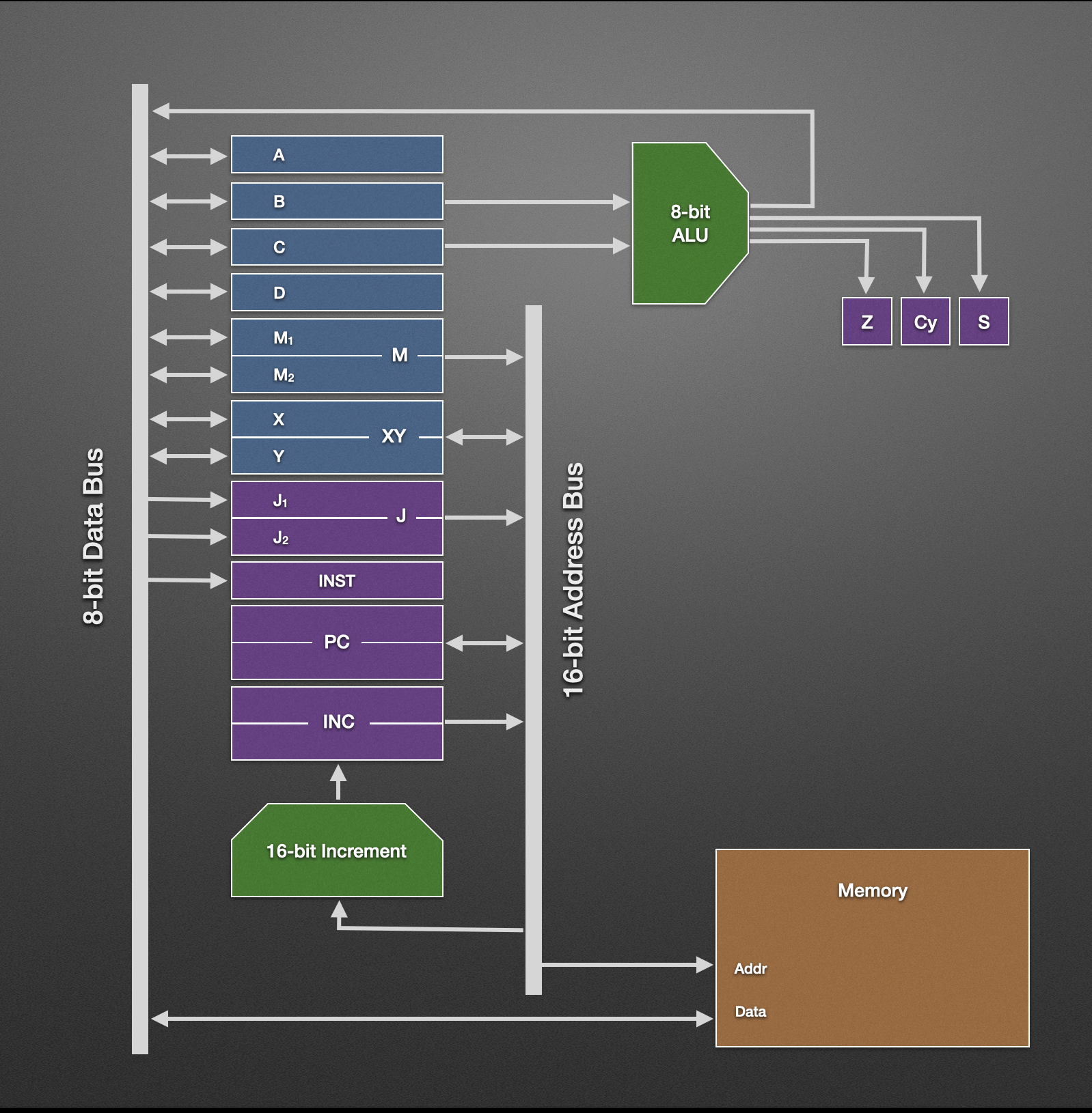
A key capability for any computer is being able to read and write data in memory and it’s the LOAD instruction that covers the first part of that. Any of the first four general purpose registers can be loaded (A, B, C or D) but a key requirement is that the 16-bit M register is set pointing to the wanted location in memory first.
There’s a few options for loading register M although typically the 16-bit load immediate is used with a known address. This is akin to how variables work in modern programming languages and, in this case at least, a variable can be thought of as just a location in memory that is holding a value of interest.
Given the destination register is 8-bits it follows that it’ll be an 8-bit value in memory loaded into the register.
Loads a value from memory into register A, B, C or D. The memory address is taken from the 16-bit M Register.
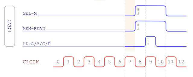
rr = destination register (00-A, 01-B, 10-C, 11-D)Here’s the LOAD timing chart:
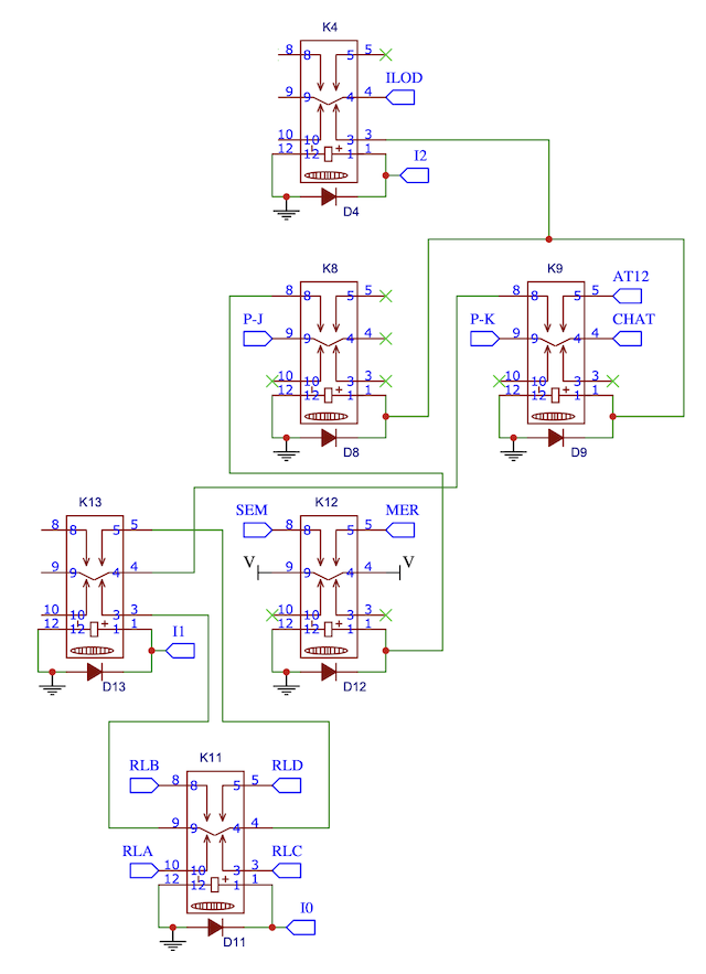
Schematic wise things follow a very similar pattern to the other instructions:
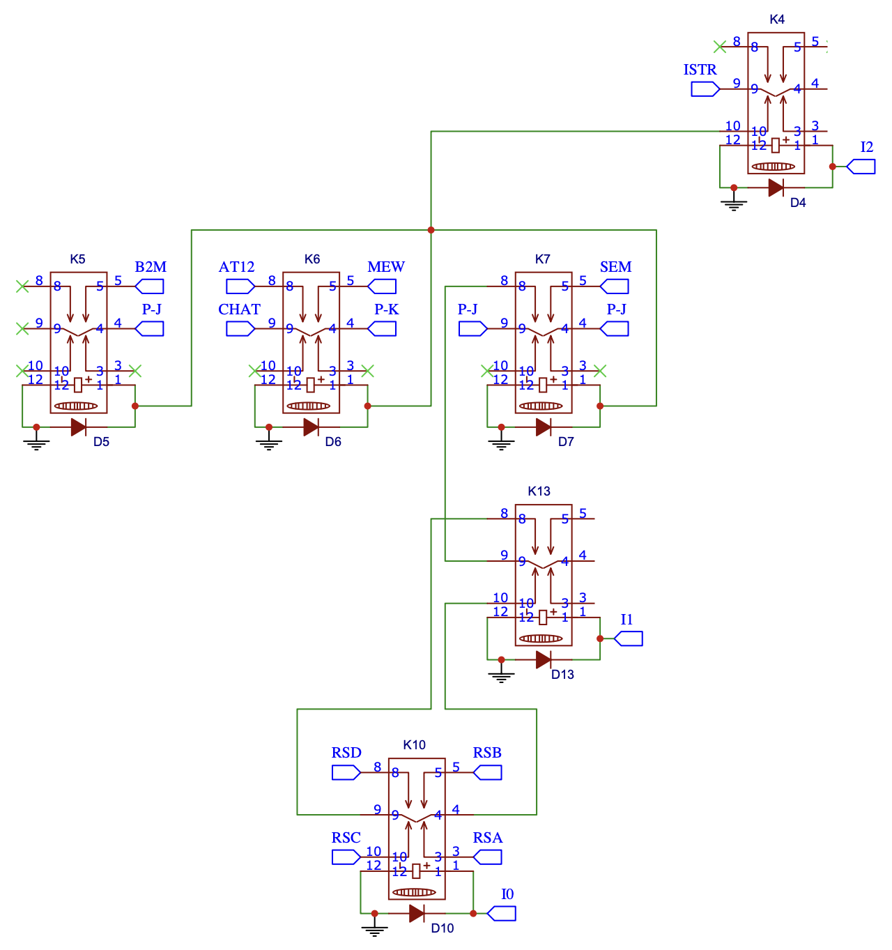
As you might expect STORE is the opposite of LOAD and stores a value in register A, B, C or D back into memory. As with LOAD the M register needs setting for the location in memory to be written to.
Stores a value in register A, B, C or D into memory. The memory address is taken from the 16-bit M Register.
rr = source register (00-A, 01-B, 10-C, 11-D)Here’s the STORE timing chart:
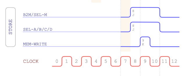
There’s a couple of things worth noting on the timing charts:
STORE and LOAD are 12 cycle instructions and the reason for the longer timing is because we have to wait for the address bus to be available following the fetch/increment cycle. Instructions like MOV-8, SETAB and ALU are 8 cycle as they can get started earlier because they’re only using the data bus.
STORE makes use of the B2M control line (Bus-to-Memory) which gates the data bus into the memory chip. This extra control line is mainly needed because of how the memory card is built and that we need to interface 12V with the 5V of the memory chip. The address bus is always gated into the memory chip but for the data bus we need to explicitly read from the chip or write to the chip - B2M marks that differentiation.
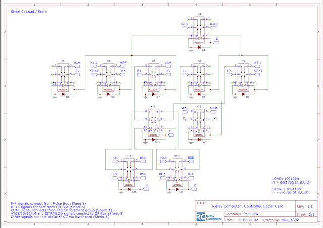
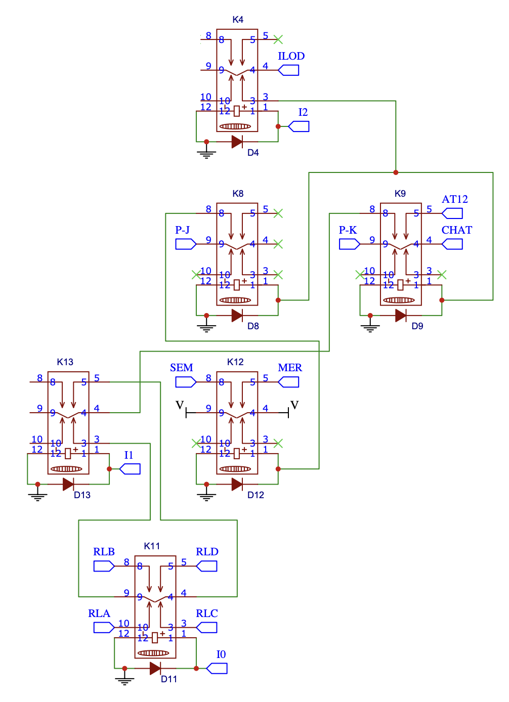
The schematic for STORE is as follows:

If you’ve got a keen eye you might notice the LOAD and STORE schematics slot together and indeed they can both be found together on page 2 of the upper controller card schematic.
So, that’s the crucial LOAD and STORE covered but we’ve still got one last instruction class to cover.
Although my relay computer is capable of various 8-bit logic and arithmetic operations there’s often a need to increment a value held in a 16-bit register. This usually happens when a register is used for ‘indexing’ memory, that is, we have a reference to a location in memory and we want to move through memory cell by cell.
You could, of course, increment each 8-bit register in turn via the ALU, say, M2 or Y followed by M1 or X but that also means you’d have to handle any carry that occurs. There’s a lot of steps involved there and given we’ve got a 16-bit half adder available in the incrementer unit it seems a shame not to take advantage. The incrementer unit is primarily used in the fetch/increment cycle to increment the program counter but nothing stops us from placing the value in a different 16-bit register.
Well, actually, there is a slight limitation. If you look at the architecture diagram you might spot it:
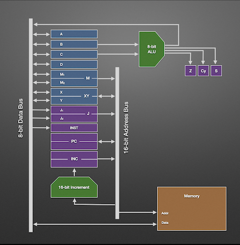
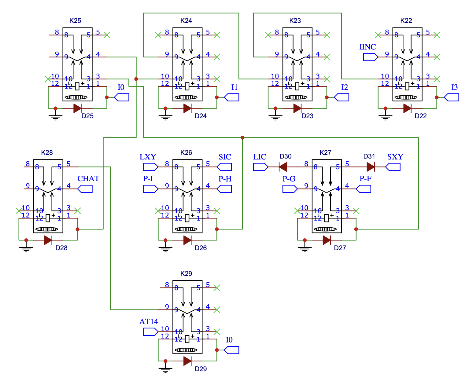
There’s only two 16-bit registers that can be written to as well as read from the address bus … the program counter and the XY register. Now, changing the program counter’s value effectively changes where the next instruction in the program will be read from. In fact, that’s exactly what the GOTO instruction relies on - load an address in to the J register and then if the jump is required then copy J to the program counter. So, the only other register that we could increment is the XY register … and that’s where we get our INCXY instruction from:
Increments the 16-bit XY register.
Here’s the INCXY timing chart:
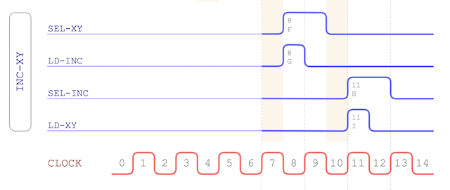
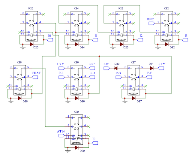
The timing for incrementing the XY register is, of course, very similar to the program counter increment at the beginning of the instruction. Schematic wise we have the following:
That’s it, that’s all the major instruction classes covered which means the controller is fully designed now and all that stands between that and a complete physical controller card is soldering in the remaining relays. That last bit of soldering also gets me to a major milestone with the relay computer - Turing completeness - and I’ll cover that a bit in the next blog post.