Well, what a journey that’s been then … I started work on a clock for my relay computer back in May 2020 and today (20th Nov 2022) this post marks the end of it. Needless to say that global pandemic got in the way a bit and hampered progress but I also, well, kind of fell out of love with my relay computer for a bit.
Like most of my hobbies I can blow ‘hot and cold’ but given I also set myself the challenge of closely detailing progress in a series of videos (all 16 of them) it was leaning me towards the ‘cold’ rather than the ‘hot’. Anyho, we’re here now and the computer finally has its clock and all card bays of the computer now have something in them.
This post is really just a bit of a ‘rounding off’ so if you’ve already been following the video series you’re pretty much up to date … if not though here’s the videos linked below. The series starts off looking at why my computer needs a clock, what a clock does and some of the options for implementing one:
Implementation wise I decided that I wanted two discrete clock options: something authentic - the relay based clock … and something flexible - the crystal based clock. I focussed first on the relay based clock and it took episodes 3 through 6 to get the basic design in place and then in episode 7 I prototyped the design on a breadboard:
With that in place I could then consider the clock control design in episode 8 and get that all prototyped in episode 9.
With the relay clock design in hand I then focussed on the crystal clock getting the design sorted in episode 10 and prototyped in episode 11:
At this point I now had my two working clock prototypes complete so it was time to draw out the schematic - a big enough task to cover a further two episodes - and then I could design the PCB based on that schematic:
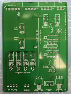
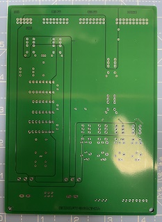
As soon as the PCBs arrived from China I cracked on with construction and testing which brings us right up to this final episode:
If you’ve been following throughout the series you’ll know things didn’t always go to plan and I intentionally left all the mistakes, mishaps and learnings in these videos so you can see what really goes on behind the scenes of designing a building a hobby project like this. Needless to say mishaps happen all the time but, actually, one of the satisfying things in building a computer made of relays is finding solutions to unexpected problems and learning as you go.
So, there we go. Will I do a mammoth video series like this again? Yea, probably but maybe not for a bit … these videos do take a lot of effort to put together but if they’re bringing enjoyment to even a handful of people then they’re worth the effort in my view.
There’s still a load more I need to do on this computer though and I’ll focus next on getting its instruction set complete next but after that there’s loads of scope for fancy ways of loading programs in to memory and for having more interesting display and output devices.
That’s for another time though so, for the clock card, here’s all that remains to do … share the designs with you all:
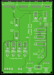
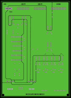
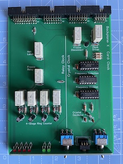
If you’d like to take a closer look at any of these you can find the full colour previews in PDF format. You can also see the schematic for the clock card (or even download the Gerber files and manufacture one of your own) at the progress page (bay X) and cards page.